
Non-destructive testing methods are commonly used
1.UT (Ultrasonic Test)
——Principle: Sound waves propagate in the material, when there are impurities of different densities in the material, sound waves will be reflected, and the piezoelectric effect of the display element will be generated on the display: the element in the probe can convert the electrical energy into mechanical energy, and the inverse effect, the mechanical energy is converted into electrical energy Ultrasonic longitudinal wave and shear wave/shear wave, the probe is divided into straight probe and oblique probe, straight probe mainly detects material, oblique probe mainly detects welds
——Ultrasonic testing equipment and operation steps
Equipment: Ultrasonic flaw detector, probe, test block
Procedure:
Brush coated couplant. Detect. Evaluate reflected signals
——Ultrasonic detection characteristics
Three-dimensional positioning is accurate, allowing only from the side of the component to operate, detection thickness of large – up to 2 meters or more, can detect the key discontinuous – flat type discontinuous, equipment easy to carry, requiring flaw detection operator level is higher, thickness is generally required not less than 8mm, smooth surface
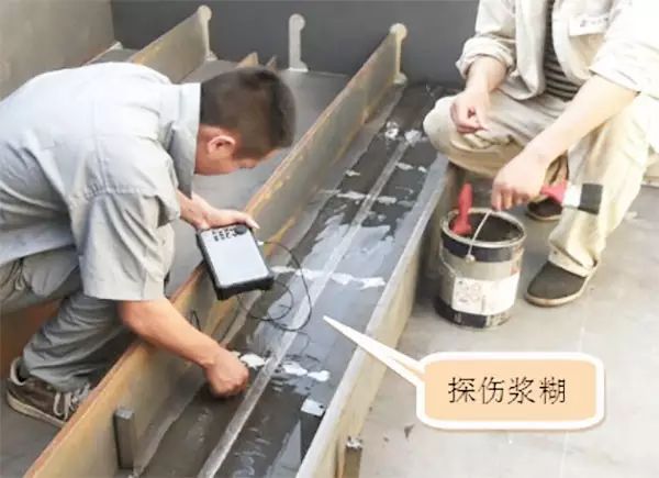
——The paste salt used for ultrasonic flaw detection is very high, and it should be cleaned up immediately after flaw detection
The paste used in ultrasonic flaw detection in the heavy industry industry has a very high salt content, and if it is not cleaned in time, it will have a great impact on the quality of the anti-corrosion coating.
For conventional anti-corrosion coatings, its main function is to isolate air or water (electrolyte) from the protected surface, but this isolation is not absolute, after a period of time, due to atmospheric pressure, air or water (electrolyte) will still enter the protected surface, then the protected surface will produce a chemical reaction with the moisture or water (electrolyte) in the air, while corroding the protected surface. Salts can be used as catalysts to accelerate corrosion rates, and the higher the salt, the faster the corrosion rate.
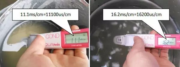
In the heavy industry industry, there is an operation – ultrasonic flaw detection, the use of paste (couplant) salt is very high, the salt content reached more than 10,000 μs / cm (the industry generally requires the salt content of the abrasive is less than 250 μs / cm, our domestic water salt is generally about 120 μs / cm), in this case, the construction of paint, the coating will lose its anti-corrosion effect in the short term.
The usual practice is to rinse off the flaw detection paste with clean water immediately after flaw detection. However, some enterprises do not attach importance to anti-corrosion, and do not clean the paste after flaw detection, resulting in difficult to remove the flaw detection paste after drying, which directly affects the anti-corrosion quality of the coating.
Here is a set of trial data:
1. Salt data of flaw detection fluid
——Principle: propagation and absorption of rays – propagation in materials or welds, absorption of rays by films
Ray absorption: thick and dense materials absorb more rays, resulting in less sensitivity of the film and whiter image. On the contrary, the image is darker
Discontinuities with black image include: slag inclusion \ air hole \ undercut \ crack \ incomplete fusion \ incomplete penetration
Discontinuities with white image: Tungsten inclusion \ spatter \ overlap \ high weld reinforcement
——RT test operation steps
Ray source location
Lay sheets on the reverse side of the weld
Exposure according to flaw detection process parameters
Film development: Developing – fixing – Cleaning – drying
Film evaluation
Open report
——Ray source, image quality indicator, blackness
Line source
X-ray: the transillumination thickness is generally less than 50mm
High energy X-ray, accelerator: the transillumination thickness is more than 200mm
γ Ray: ir192, Co60, Cs137, ce75, etc., with transillumination thickness ranging from 8 to 120mm
Linear image quality indicator
Hole type image quality indicator must be used for FCM of bridge
Blackness d=lgd0/d1, another index for evaluating film sensitivity
X-ray radiographic requirements: 1.8~4.0; γ Radiographic requirements: 2.0~4.0,
——RT equipment
Ray source: X-ray machine or γ X-ray machine
Ray alarm
Loading bag
Image quality indicator: line type or pass type
Blackness meter
Film developing machine
(oven)
Film viewing lamp
(exposure room)
——RT features
Applicable to all materials
Records (negatives) are easy to save
Radiation damage to human body
Directivity of discontinuities:
1. sensitivity to discontinuities parallel to the beam direction
2. insensitive to discontinuities parallel to the material surface
Type of discontinuity:
It is sensitive to three-dimensional discontinuities (such as pores), and it is easy to miss inspection for plane discontinuities (such as incomplete fusion and cracks) The data show that the detection rate of RT for cracks is 60%
RT of most components shall be accessed from both sides
Negatives shall be evaluated by experienced personnel
3.mt (magnetic particle inspection)
——Principle: after the workpiece is magnetized, the magnetic leakage field is generated at the discontinuity, and the magnetic particle is adsorbed to form the magnetic trace display
Magnetic field: permanent magnetic field and electromagnetic field generated by permanent magnet
Magnetic particle: dry magnetic particle and wet magnetic particle
Magnetic particle with color: black magnetic particle, red magnetic particle, white magnetic particle
Fluorescent magnetic powder: irradiated by ultraviolet lamp in the dark room, it is yellow green and has the highest sensitivity
Directivity: discontinuities perpendicular to the direction of the magnetic line of force are the most sensitive
——Common magnetization methods
Longitudinal magnetization: yoke method, coil method
Circumferential magnetization: contact method, central conductor method
Magnetizing current:
AC: high sensitivity to surface discontinuities
DC: high sensitivity to near surface discontinuities
——Magnetic particle testing procedure
Cleaning workpiece
Magnetized workpiece
Apply magnetic particle while magnetizing
Interpretation and evaluation of magnetic trace
Cleaning workpiece
(demagnetization)
——MT features
High sensitivity
efficient
Yoke method and other equipment are easy to move
Near surface discontinuities can be detected compared to penetration
Low cost
Only applicable to ferromagnetic materials, not applicable to austenitic stainless steel, aluminum alloy, titanium alloy, copper and copper alloy
It is sensitive to the coating on the workpiece surface. Generally, the coating thickness shall not exceed 50um
Sometimes components need demagnetization
4.pt (penetrant inspection)
——Principle: use capillarity to suck back the penetrant remaining in the discontinuity, so that the penetrant (usually red) and the imaging liquid (usually white) are mixed to form a display
——Penetrant inspection type
According to the type of image formed:
Coloration, visible light
Fluorescence, UV
According to the method of removing excess penetrant:
Solvent removal
Water washing method
Post emulsification
The most commonly used method in steel structure is: colored solvent removal method
——Test steps
Cleaning workpiece: use cleaning agent
Apply penetrant and keep it for 2~20min. Adjust it according to the ambient temperature. If the time is too short, the penetrant is incomplete, too long or the temperature is too high, the penetrant will dry The penetrant shall be kept wet throughout the test
Remove excess penetrant with cleaning agent. It is forbidden to spray cleaning agent directly on the workpiece. Wipe it with clean cloth or paper dipped with penetrant from one direction to avoid taking away the discontinuous penetrant through cleaning
Apply a uniform and thin layer of developer solution with a spraying interval of about 300mm. Too thick developer solution may cause discontinuity
Explain and assess discontinuities
Cleaning workpiece
——PT features
The operation is simple
For all metals
High sensitivity
Very easy to move
Detection of open surface discontinuities only
Low work efficiency
High surface grinding requirements
environment pollution
Adaptability of various inspections to defect location
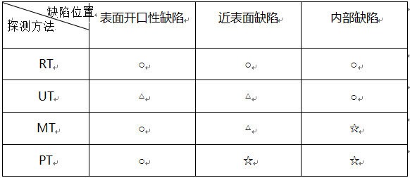
Note: ○ — appropriate △ — General ☆ — difficult
Adaptability of various tests to the shape of detected defects
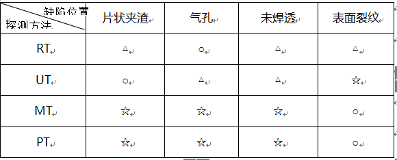
Note: ○ — appropriate △ — General ☆ — difficult
Post time: Jun-06-2022