
Requirements for Welded Backing Plates by Standard
Among the welded joint forms of steel structures, the joint form using backing plates is more common. The use of backing plates can solve welding problems in tight and confined spaces and reduce the difficulty of welding operations. Conventional backing plate materials are divided into two types: steel backing and ceramic backing. Of course, in some cases, materials such as flux are used as backing. This article describes the issues that need to be paid attention to when using steel gaskets and ceramic gaskets.
National Standard—–GB 50661
Clause 7.8.1 of GB50661 stipulates that the yield strength of the backing plate used should not be greater than the nominal strength of the steel to be welded, and the weldability should be similar.
However, it is worth noting that clause 6.2.8 stipulates that backing boards of different materials cannot be substituted for each other. (Steel liners and ceramic liners are not substitutes for each other).
European Standard—–EN1090-2
Clause 7.5.9.2 of EN1090-2 stipulates that when using a steel backing, the carbon equivalent is required to be less than 0.43%, or a material with the highest weldability as the base metal to be welded.
American Standard—-AWS D 1.1
The steel used for the backing plate must be any of the steels in Table 3.1 or Table 4.9, if not in the list, except that the steel with a minimum yield strength of 690Mpa is used as the backing plate which must only be used for welding of steel with a minimum yield strength of 690Mpa , must be steel that has been assessed. Engineers should note that the general backing board purchased in China is Q235B. If the base material at the time of evaluation is Q345B, and the backing board is generally replaced by the clean root, the material of the backing board is Q235B when preparing WPS. In this case, the Q235B has not been evaluated, so this WPS is not in compliance with the regulations.
Interpretation of the coverage of the EN standard welder exam
In recent years, the number of steel structure projects produced and welded according to the EN standard is increasing, so that the demand for welders of the EN standard is increasing. However, many steel structure manufacturers are not particularly clear about the coverage of the EN welder test, resulting in more tests. There are a lot of missed exams. These will affect the progress of the project, and when the weld is to be welded it is discovered that the welder is not qualified to weld.
This article briefly introduces the coverage of the welder exam, hoping to bring help to everyone’s work.
1. Welder Exam Execution Standards
a) Manual and semi-automatic welding: EN 9606-1 (Steel construction)
For EN9606 series is divided into 5 parts. 1—steel 2—aluminum 3—copper 4—nickel 5—zirconium
b) Machine welding: EN 14732
The division of welding types refers to ISO 857-1
2. Material Coverage
For the coverage of the base metal, there is no clear regulation in the standard, but there are coverage regulations for the welding consumables.
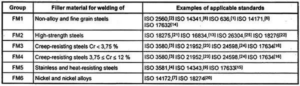
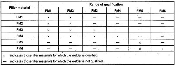
Through the above two tables, the grouping of welding consumables and the coverage between each group can be clear.
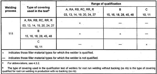
Electrode Welding (111) Coverage
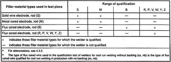
Coverage for different wire types
3. Base metal thickness and pipe diameter coverage
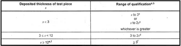
Docking Specimen Coverage
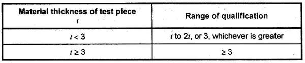
Fillet Weld Coverage
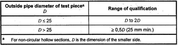
Steel Pipe Diameter Coverage
4. Welding position coverage
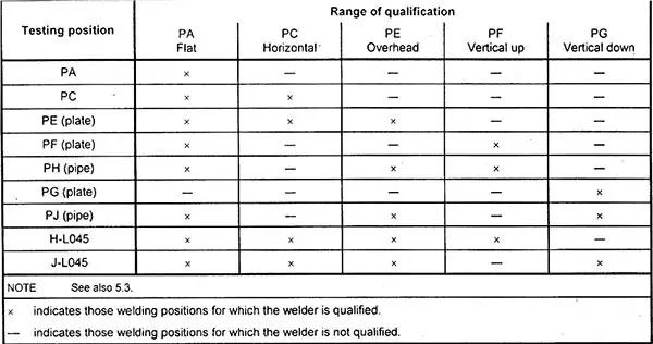
Docking Specimen Coverage
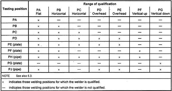
Fillet Weld Coverage
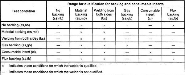
5. Node Form Coverage
The welded backing plate and the root-cleaning weld can cover each other, so in order to reduce the difficulty of the test, the test joint welded by the backing plate is generally selected.
6. Weld layer coverage
Multi-layer welds can replace single-layer welds, but not vice versa.
7. Other Notes
a) Butt welds and fillet welds are not interchangeable.
b) The butt joint can cover the branch pipe welds with an included angle greater than or equal to 60°, and the coverage is limited to the branch pipe
The outer diameter shall prevail, but the wall thickness shall be defined according to the range of the wall thickness.
c) Steel pipes with an outer diameter greater than 25mm can be covered with steel plates.
d) Plates can cover steel pipes with a diameter greater than 500mm.
e) The plate can be covered with steel pipes with a diameter greater than 75mm in the rotating condition, but the welding position
At the location of PA, PB, PC, PD.
8. Inspection
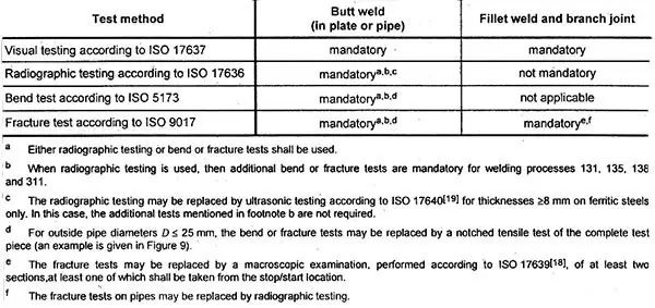
For appearance and macro inspection, it is tested according to EN5817 B level, but the code is 501, 502, 503, 504, 5214, according to C level.
picture
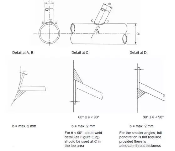
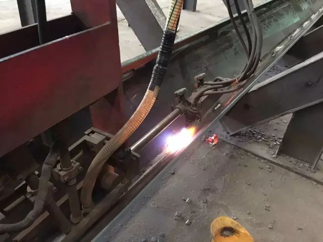
EN Standard Intersecting Line Welding Requirements
In projects with many types of steel pipes or square steels, the welding requirements of intersecting lines are relatively high. Because if the design requires full penetration, it is not easy to add a liner plate inside the straight pipe, and due to the difference in the roundness of the steel pipe, the cut intersecting line cannot be completely qualified, resulting in manual repairing in the follow-up. In addition, the angle between the main pipe and the branch pipe is too small, and the root area cannot be penetrated.
For the above three situations, the following solutions are recommended:
1) There is no backing plate for the intersecting line weld, which is equivalent to full penetration of the weld on one side. It is recommended to weld at the 1 o’clock position and use the solid core gas shielding method for welding. The welding gap is 2-4mm, which can not only ensure penetration, but also prevent welding through.
2) The intersecting line is unqualified after cutting. This problem can only be adjusted manually after machine cutting. If necessary, pattern paper can be used to paint the intersecting line cutting line on the outside of the branch pipe, and then directly cut by hand.
3) The problem that the angle between the main pipe and the branch pipe is too small to be welded is explained in Appendix E of EN1090-2. For intersecting line welds, it is divided into 3 parts: toe, transition zone, root. The toe and transition zone are impure in the case of poor welding, only the root has this condition. When the distance between the main pipe and the branch pipe is less than 60°, the root weld can be a fillet weld.
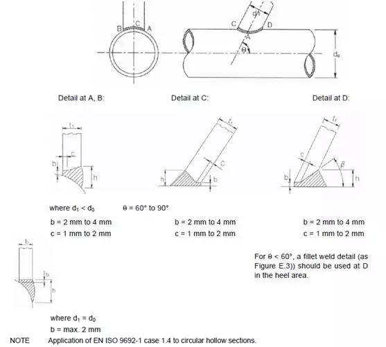
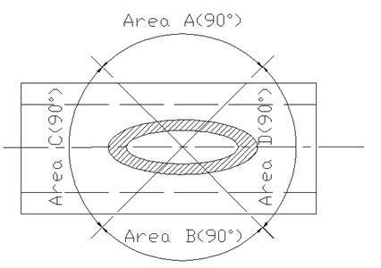
However, the area division of A, B, C, and D in the figure is not clearly pointed out in the standard. It is recommended to explain it according to the following figure:
Common cutting methods and process comparison
Common cutting methods mainly include flame cutting, plasma cutting, laser cutting and high-pressure water cutting, etc. Each process method has its own advantages and disadvantages. When processing products, an appropriate cutting process method should be selected according to the specific situation.
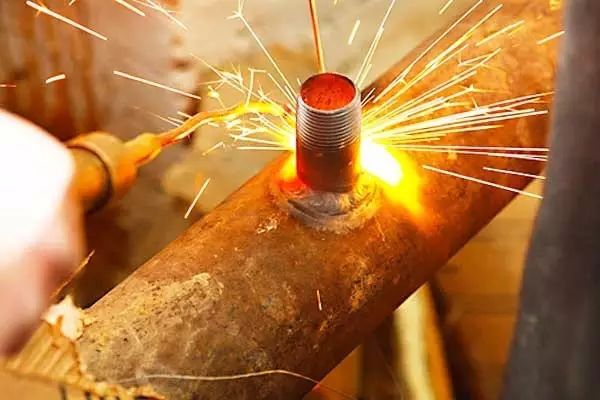
1. Flame cutting: After preheating the cutting part of the workpiece to the combustion temperature by the heat energy of the gas flame, a high-speed cutting oxygen flow is sprayed to make it burn and release heat for cutting.
a) Advantages: The cutting thickness is large, the cost is low, and the efficiency has obvious advantages after the thickness exceeds 50mm. The slope of the section is small (< 1°), and the maintenance cost is low.
b) Disadvantages: low efficiency (speed 80~1000mm/min within 100mm thickness), only used for low carbon steel cutting, cannot cut high carbon steel, stainless steel, cast iron, etc., large heat affected zone, serious deformation of thick plates, difficult operation big.
2. Plasma cutting: a method of cutting by using gas discharge to form the thermal energy of plasma arc. When the arc and the material burn, heat is generated so that the material can be continuously burned through the cutting oxygen and discharged by the cutting oxygen to form a cut.
a) Advantages: The cutting efficiency within 6~20mm is the highest (speed is 1400~4000mm/min), and it can cut carbon steel, stainless steel, aluminum, etc.
b) Disadvantages: the incision is wide, the heat affected zone is large (about 0.25mm), the deformation of the workpiece is obvious, the cutting shows serious twists and turns, and the pollution is large.
3. Laser cutting: a process method in which a high-power density laser beam is used for local heating to evaporate the heated part of the material to achieve cutting.
a) Advantages: narrow cutting width, high precision (up to 0.01mm), good cutting surface roughness, fast cutting speed (suitable for thin sheet cutting), and small heat affected zone.
b) Disadvantages: high equipment cost, suitable for thin plate cutting, but the efficiency of thick plate cutting is obviously reduced.
4. High-pressure water cutting: a process method that uses high-pressure water speed to achieve cutting.
a) Advantages: high precision, can cut any material, no heat affected zone, no smoke.
b) Disadvantages: high cost, low efficiency (speed 150~300mm/min within 100mm thickness), only suitable for plane cutting, not suitable for three-dimensional cutting.
What is the optimal diameter of the parent bolt hole and what is the optimal gasket thickness and size required?
Table 14-2 in the 13th edition of the AISC Steel Building Handbook discusses the maximum size of each bolt hole in the parent material. It should be noted that the hole sizes listed in Table 14-2 allow certain deviations of the bolts during the installation process, and the base metal adjustment needs to be more precise or the column needs to be installed precisely on the centerline. It is important to note that flame cutting is usually required to handle these hole sizes. A qualified washer is required for each bolt. Since these hole sizes are specified as the maximum value of their respective sizes, smaller hole sizes can often be used for accurate classification of bolts.
The AISC Design Guide 10, Low Rise Steel Frame Support Column Installation section, based on past experience, sets the following reference values for gasket thickness and size: the minimum gasket thickness should be 1/3 the diameter of the bolt, and the minimum gasket diameter ( or non-circular washer length and width) should be 25.4mm (1 in.) larger than the hole diameter. When the bolt transmits tension, the washer size should be large enough to transmit the tension to the base metal. In general, the appropriate gasket size can be determined according to the size of the steel plate.
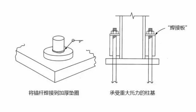
Can the bolt be welded directly to the base metal?
If the bolt material is weldable, it can be welded to the base metal. The main purpose of using an anchor is to provide a stable point for the column to ensure its stability during installation. In addition, bolts are used to connect statically loaded structures to resist supporting forces. Welding the bolt to the base metal does not accomplish either of the above purposes, but it helps to provide pullout resistance.
Because the size of the base metal hole is too large, the anchor rod is rarely set in the center of the base metal hole. In this case, a thick plate gasket (as shown in the figure) is required. Welding the bolt to the gasket involves the appearance of the fillet weld, such as the length of the weld equal to the perimeter of the bolt [π(3.14) times the diameter of the bolt], in which case the produces relatively little intensity. But it is allowed to weld the threaded part of the bolt. If more support occurs, the details of the column base can be changed, taking into account the “welded plate” listed in the image below.
What is the optimal diameter of the parent bolt hole and what is the optimal gasket thickness and size required?
The importance of tack welding quality
In the production of steel structures, the welding process, as an important part of ensuring the quality of the entire project, has received great attention. However, tack welding, as the first link of the welding process, is often ignored by many companies. The main reasons are:
1) Positioning welding is mostly done by assemblers. Due to skills training and process allocation, many people think that it is not a welding process.
2) The tack welding seam is hidden under the final welding seam, and many defects are covered up, which cannot be found during the final inspection of the welding seam, which has no effect on the final inspection result.
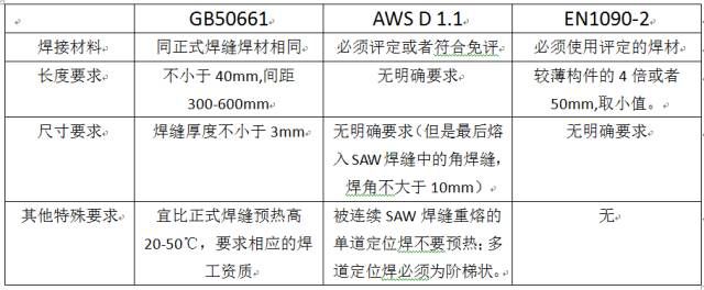
▲ too close to the end (error)
Are tack welds important? How much does it affect the formal weld? In production, first of all, it is necessary to clarify the role of positioning welds: 1) Fixing between parts plates 2) It can bear the weight of its components during transportation.
Different standards require tack welding:
Combining the requirements of each standard for tack welding, we can see that the welding materials and welders of tack welding are the same as the formal weld, which is enough to see the importance.
▲At least 20mm from the end (correct)
The length and size of tack welding can be determined according to the thickness of the part and the form of components, unless there are strict restrictions in the standard, but the length and thickness of tack welding should be moderate. If it is too large, it will increase the difficulty of the welder and make it difficult to ensure quality. For fillet welds, an excessively large tack weld size will directly affect the appearance of the final weld, and it is easy to appear wavy. If it is too small, it is easy to cause the tack weld to crack during the transfer process or when the reverse side of the tack weld is welded. In this case, the tack weld must be completely removed.
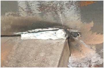
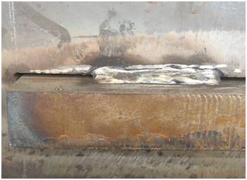
▲ Tack welding crack (error)
For the final weld that requires UT or RT, the defects of tack welding can be found, but for fillet welds or partial penetration welds, welds that do not need to be inspected for internal defects, the defects of tack welding are ” “Time bomb”, which is likely to explode at any time, causing problems such as cracking of welds.
What is the purpose of post weld heat treatment?
There are three purposes of post-weld heat treatment: eliminating hydrogen, eliminating welding stress, improving weld structure and overall performance. Post-weld dehydrogenation treatment refers to the low-temperature heat treatment performed after the welding is completed and the weld has not been cooled to below 100 °C. The general specification is to heat to 200~350℃ and keep it for 2-6 hours. The main function of post-weld hydrogen elimination treatment is to accelerate the escape of hydrogen in the weld and heat-affected zone, which is extremely effective in preventing welding cracks during welding of low-alloy steels.
During the welding process, due to the non-uniformity of heating and cooling, and the restraint or external restraint of the component itself, welding stress will always be generated in the component after the welding work is completed. The existence of welding stress in the component will reduce the actual bearing capacity of the welded joint area, cause plastic deformation, and even lead to the damage of the component in severe cases.
Stress relief heat treatment is to reduce the yield strength of the welded workpiece at high temperature to achieve the purpose of relaxing the welding stress. There are two commonly used methods: one is the overall high temperature tempering, that is, the whole weldment is put into the heating furnace, slowly heated to a certain temperature, then kept for a period of time, and finally cooled in the air or in the furnace. In this way, 80%-90% of welding stress can be eliminated. Another method is local high temperature tempering, that is, only heating the weld and its surrounding area, and then slowly cooling, reducing the peak value of the welding stress, making the stress distribution relatively flat, and partially eliminating the welding stress.
After some alloy steel materials are welded, their welded joints will have a hardened structure, which will deteriorate the mechanical properties of the material. In addition, this hardened structure may lead to the destruction of the joint under the action of welding stress and hydrogen. After heat treatment, the metallographic structure of the joint is improved, the plasticity and toughness of the welded joint are improved, and the comprehensive mechanical properties of the welded joint are improved.
Do arc damage and temporary welds melted into permanent welds need to be removed?
In statically loaded structures, arcing damages do not need to be removed unless the contract documents expressly require them to be removed. However, in dynamic structures, arcing can cause excessive stress concentration, which will destroy the durability of the dynamic structure, so the surface of the structure should be ground flat and cracks on the surface of the structure should be visually inspected. For more details on this discussion, please refer to Section 5.29 of AWS D1.1:2015.
In most cases, temporary joints on tack welds can be incorporated into permanent welds. Generally, in statically loaded structures, it is permissible to retain those tack welds that cannot be incorporated unless the contract documents specifically require them to be removed. In dynamically loaded structures, temporary tack welds must be removed. For more details on this discussion, please refer to Section 5.18 of AWS D1.1:2015.
[1] Statically loaded structures are characterized by very slow application and movement, which is common in buildings
[2] Dynamically loaded structure refers to the process of applying and/or moving at a certain speed, which cannot be regarded as static and requires consideration of metal fatigue, which is common in bridge structures and crane rails.
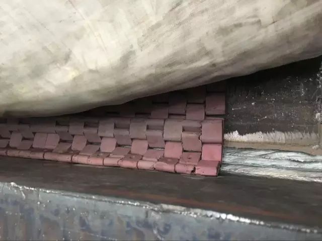
Precautions for winter welding preheating
The cold winter has come, and it also puts forward higher requirements for welding preheating. The preheat temperature is usually measured before soldering, and maintaining this minimum temperature during soldering is often overlooked. In winter, the cooling speed of the weld joint is fast. If the control of the minimum temperature in the welding process is ignored, it will bring serious hidden dangers to the welding quality.
Cold cracks are the most and the most dangerous among the welding defects in winter. The three main factors for the formation of cold cracks are: hardened material (base metal), hydrogen, and degree of restraint. For conventional structural steel, the reason for the hardening of the material is that the cooling rate is too fast, so increasing the preheating temperature and maintaining this temperature can solve this problem well.
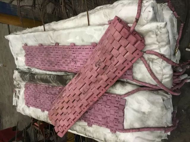
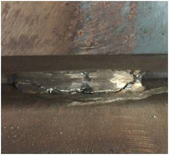
In general winter construction, the preheating temperature is 20℃-50℃ higher than the conventional temperature. Special attention should be paid to the preheating of the positioning welding of the thick plate is slightly higher than that of the formal weld. For electroslag welding, submerged arc welding and other heat input Higher soldering methods can be the same as conventional preheating temperatures. For long components (generally larger than 10m), it is not recommended to evacuate the heating equipment (heating tube or electric heating sheet) during the welding process to prevent the situation of “one end is hot and the other end is cold”. In the case of outdoor operations, after the welding is completed, heat preservation and slow cooling measures should be taken to the weld area.
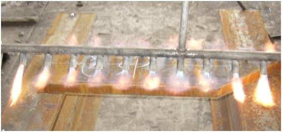
Welding preheat tubes (for long members)
It is recommended to use low-hydrogen welding consumables in winter. According to AWS, EN and other standards, the preheating temperature of low-hydrogen welding consumables can be lower than that of general welding consumables. Pay attention to the formulation of the welding sequence. A reasonable welding sequence can greatly reduce the welding restraint. At the same time, as a welding engineer, it is also the responsibility and obligation to review the welding joints in the drawings that may cause great restraint, and coordinate with the designer to change the joint form.
After soldering, when should the solder pads and pinout plates be removed?
In order to ensure the geometrical integrity of the welded joint, after the completion of welding, the lead-out plate at the edge of the component may need to be cut off. The function of the lead-out plate is to ensure the normal size of the weld from the beginning to the end of the welding process; but the above process needs to be followed. As specified in Sections 5.10 and 5.30 of AWS D1.1 2015. When it is necessary to remove welding auxiliary tools such as welding pads or lead-out plates, the treatment of the welding surface needs to be carried out according to the relevant requirements of pre-welding preparation.
The 1994 North Ridge Earthquake resulted in the destruction of the “beam-column-section steel” welded connection structure, drawing attention and discussion on welding and seismic details, and on the basis of which new standard conditions were established. The provisions on earthquakes in the 2010 edition of the AISC standard and the corresponding Supplement No. 1 include clear requirements in this regard, that is, whenever seismic engineering projects are involved, the welding pads and lead-out plates need to be removed after welding. There is an exception, however, where the performance retained by the tested component still proves to be acceptable by handling other than the above.
Improving Cut Quality – Considerations in Programming and Process Control
With the rapid development of the industry, it is particularly important to improve the cutting quality of parts. There are many factors that affect cutting, including cutting parameters, the type and quality of gas used, the technical ability of the workshop operator, and the understanding of the cutting machine equipment.
(1) The correct use of AutoCAD to draw part graphics is an important prerequisite for the quality of cutting parts; nesting typesetting personnel compile CNC cutting part programs in strict accordance with the requirements of part drawings, and reasonable measures should be taken when programming some flange splicing and slender parts : Soft compensation, special process (co-edge, continuous cutting), etc., to ensure that the size of the parts after cutting passes the inspection.
(2) When cutting large parts, because the central column (conical, cylindrical, web, cover) in the round stack is relatively large, it is recommended that programmers perform special processing during programming, micro-connection (increase breakpoints) , that is, set the corresponding temporary non-cutting point (5mm) on the same side of the part to be cut. These points are connected with the steel plate during the cutting process, and the parts are held to prevent displacement and shrinkage deformation. After the other parts are cut, these points are cut to ensure that the size of the cut parts is not easily deformed.
Strengthening the process control of cutting parts is the key to improving the quality of cutting parts. After a large amount of data analysis, the factors that affect the cutting quality are as follows: operator, selection of cutting nozzles, adjustment of the distance between cutting nozzles and workpieces, and adjustment of cutting speed , and the perpendicularity between the surface of the steel plate and the cutting nozzle.
(1) When operating the CNC cutting machine to cut parts, the operator must cut the parts according to the blanking cutting process, and the operator is required to have self-inspection awareness and be able to distinguish between qualified and unqualified parts for the first part cut by himself, if unqualified Correct and repair in time; then submit it to quality inspection, and sign the first qualified ticket after passing the inspection; only then can mass production of cutting parts.
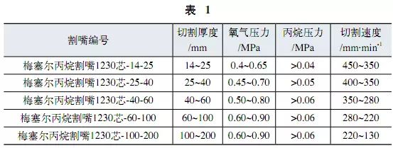
(2) The model of the cutting nozzle and the distance between the cutting nozzle and the workpiece are all reasonably selected according to the thickness of the cutting parts. The larger the cutting nozzle model, the thicker the thickness of the steel plate normally cut; and the distance between the cutting nozzle and the steel plate will be affected if it is too far or too close: too far will cause the heating area to be too large, and also increase the thermal deformation of the parts; If it is too small, the cutting nozzle will be blocked, resulting in waste of wearing parts; and the cutting speed will also be reduced, and the production efficiency will also be reduced.
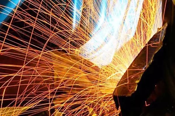
(3) The adjustment of the cutting speed is related to the thickness of the workpiece and the selected cutting nozzle. Generally, it slows down with the increase of the thickness. If the cutting speed is too fast or too slow, it will affect the quality of the cutting port of the part; a reasonable cutting speed will produce a regular popping sound when the slag flows, and the slag outlet and the cutting nozzle are basically in a line; a reasonable cutting speed It will also improve the production cutting efficiency, as shown in Table 1.
(4) The perpendicularity between the cutting nozzle and the surface of the steel plate of the cutting platform, if the cutting nozzle and the surface of the steel plate are not perpendicular, will cause the part section to be inclined, which will affect the uneven size of the upper and lower parts of the part, and the accuracy cannot be guaranteed. Accidents; the operator should check the permeability of the cutting nozzle in time before cutting. If it is blocked, the airflow will be inclined, causing the cutting nozzle and the surface of the cutting steel plate to be non-perpendicular, and the size of the cutting parts will be wrong. As an operator, the cutting torch and cutting nozzle should be adjusted and calibrated before cutting to ensure that the cutting torch and cutting nozzle are perpendicular to the surface of the steel plate of the cutting platform.
The CNC cutting machine is a digital program that drives the movement of the machine tool. When the machine tool moves, the randomly equipped cutting tool cuts the parts; so the programming method of the parts on the steel plate plays a decisive factor in the processing quality of the cut parts.
(1) Optimizing the nesting cutting process is based on the optimized nesting diagram, which is converted from the nesting state to the cutting state. By setting the process parameters, the contour direction, the starting point of the inner and outer contours, and the lead-in and lead-out lines are adjusted. To achieve the shortest idle path, reduce thermal deformation during cutting, and improve cutting quality.
(2) The special process of optimizing nesting is based on the outline of the part on the layout drawing, and designing the cutting trajectory to meet the actual needs through the “descriptive” operation, such as anti-deformation micro-joint cutting, multi-part continuous cutting, bridge cutting, etc., Through optimization, cutting efficiency and quality can be better improved.
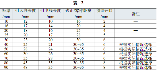
(3) Reasonable selection of process parameters is also very important. Choose different cutting parameters for different plate thicknesses: such as the selection of lead-in lines, the selection of lead-out lines, the distance between parts, the distance between the edges of the plate and the size of the reserved opening. Table 2 is Cutting parameters for each plate thickness.
The important role of welding shielding gas
From a technical point of view, just by changing the shielding gas composition, the following 5 important influences can be made on the welding process:
(1) Improve the welding wire deposition rate
Argon-enriched gas mixtures generally result in higher production efficiencies than conventional pure carbon dioxide. Argon content should exceed 85% to achieve jet transition. Of course, increasing the welding wire deposition rate requires the selection of appropriate welding parameters. The welding effect is usually the result of the interaction of multiple parameters. Inappropriate selection of welding parameters will usually reduce the welding efficiency and increase the slag removal work after welding.
(2) Control spatter and reduce slag cleaning after welding
The low ionization potential of argon increases arc stability with a corresponding reduction in spatter. Recent new technology in welding power sources has controlled spatter in CO2 welding, and under the same conditions, if a gas mixture is used, spatter can be further reduced and the welding parameter window can be expanded.
(3) Control weld formation and reduce excessive welding
CO2 welds tend to protrude outwards, resulting in overwelding and increased welding costs. The argon gas mixture is easy to control the weld formation and avoids the waste of welding wire.
(4) Increase the welding speed
By using an argon-rich gas mixture, spatter remains very well controlled even with increased welding current. The advantage this brings is an increase in welding speed, especially for automatic welding, which greatly improves production efficiency.
(5) Control welding fume
Under the same welding operating parameters, the argon-rich mixture greatly reduces welding fumes compared to carbon dioxide. Compared to investing in hardware equipment to improve the welding operating environment, the use of an argon-rich gas mixture is an attendant advantage of reducing contamination at the source.
At present, in many industries, argon gas mixture has been widely used, but due to herd reasons, most domestic enterprises use 80%Ar+20%CO2. In many applications, this shielding gas does not work optimally. Therefore, choosing the best gas is actually the easiest way to improve the product management level for a welding enterprise on the way forward. The most important criterion for choosing the best shielding gas is to meet the actual welding needs to the greatest extent. In addition, proper gas flow is the premise to ensure welding quality, too large or too small flow is not conducive to welding
Post time: Jun-07-2022