
1. Matters needing attention in the review of the welding material warranty
Welding Material Warranty Book is very important as a written document and record of welding material quality assurance. Welding materials must be checked for compliance with the requirements before use. The welding material warranty book is equivalent to the “delivery information” provided by the welding material manufacturer to the user, and its content should be accurate and complete.
At present, there are many domestic welding consumable manufacturers, and the quality of their products varies. The format and content of product warranty documents are also different. For welding engineers or quality engineers, it is also very important to check the warranty documents.
This article takes the AWS standard warranty as an example to briefly introduce the key points to note when reviewing the warranty.
1) The standard number corresponds to the welding material model
All the values in the American Standard welding consumable standards are divided into imperial and metric systems, and the metric system is added with “M” after the standard number.
For example, submerged arc welding wire AWS A 5.17 / AWS A 5.17M
This is the correct way of writing, the standard number is imperial, and the model is also imperial.
2) The implementation standard of the warranty book should be consistent with the actual demand (purchase order)
If American standard welding consumables are required, the above writing is incorrect and cannot be equivalent to American standard, because the standard values or experimental methods of different standards are different.
3) Expression of qualified standard values and experimental values
The above is the value of the American standard warranty book for submerged arc welding wire, but the implementation standard in the warranty book is AWS A 5.17. From the standard number, it can be seen that all the values should be in English. However, the standard values and experimental data in the warranty book are in metric system, which is obviously not standardized.
For example, the impact temperature of F7A2-EH14 should be -20°F, which is -28.8°C in Celsius, but the standard value is -30°C.
Based on the above reasons, it is very important for engineers to check whether there is an “M” in the standard number when reviewing the warranty book. Only with the specification of the warranty book can the welding wire be put into actual production.
2. Appearance acceptance criteria for each specification
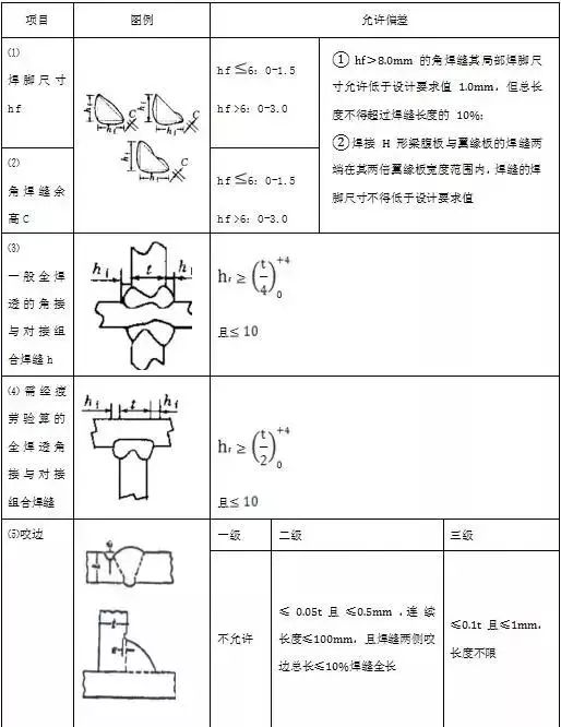
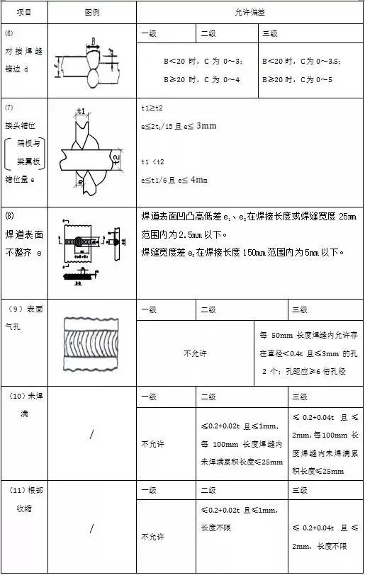
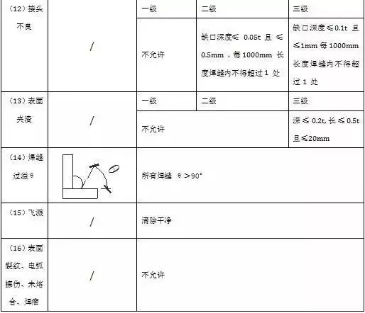
(1) GB standard appearance acceptance criteria
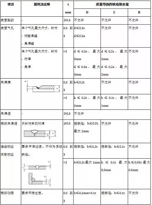
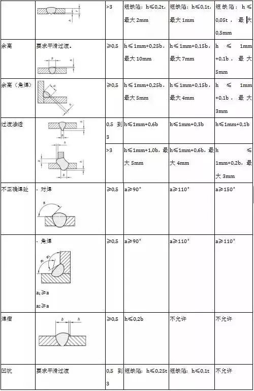
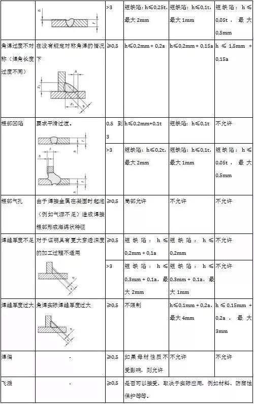
(1) EN standard appearance acceptance criteria
—EXC1 quality class D;
— EXC2 Generally, quality class C,
— EXC3 quality class B;
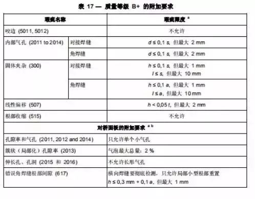
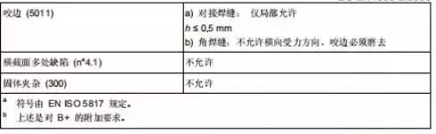
— EXC4 Quality class B+, which means additional requirements on the basis of quality class B
(2) AWS Standard Appearance Acceptance Criteria
Weld profile requirements
Visual inspection standard
Acceptance Conditions for Continuity Types and Inspections
static load
cyclic load
(1) Cracks are prohibited
Any cracks, regardless of size or location, are not acceptable.
X
X
(2) Weld/base metal fusion
There must be complete fusion between adjacent layers of the weld and between the weld metal and the base metal.
X
X
(3) Arc crater cross section
All arc craters must be filled to the specified weld size, except at the ends of intermittent fillet welds that exceed the effective length of the intermittent fillet weld.
X
X
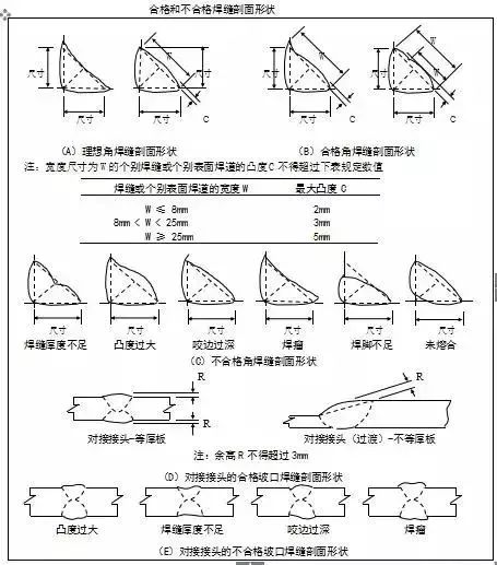
(4) Weld profile shape
Weld profile shape must conform to “Pass and Fail Weld Profile Shape (AWSD1.1-2000)”
X
X
(5) Inspection time
Visual inspection of all steel welds can begin as soon as the finished weld has cooled to ambient room temperature. Acceptance of ASTM A514, A517 and A709 Grades 100 and 100W steel welds must be based on visual inspection at least 48 hours after the weld is completed.
X
X
(6) Insufficient weld size
The size of any continuous fillet weld which is less than the specified nominal size (L) and meets the following specified values (U) may not be compensated:
L U
Specified nominal weld size (mm) Allowable reduction on the basis of L (mm)
≤ 5 ≤ 1.6
6 ≤ 2.5
≥ 8 ≤ 3
In all cases, the undersized part of the weld is strictly prohibited to exceed 10% of the length of the weld. The welding seam connecting the web of the girder and the flange shall not be insufficient in size within the range of the two ends of the beam and the length equal to twice the width of the flange.
X
X
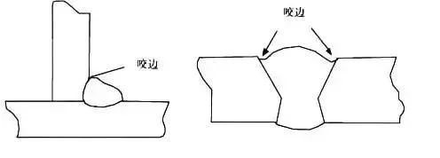
(7) Undercut
(A) Undercuts on materials with a thickness of less than 25mm are strictly prohibited to exceed 0.8mm, but undercuts with a cumulative undercut of 50mm and a maximum of 1.5mm in any 300mm length are allowed. For materials with a thickness equal to or greater than 25mm, the undercut of any length of weld is strictly prohibited to exceed 1.5mm
X
(B) In the main components, under any design load, when the weld is in a transverse relationship with the tensile stress, the undercut depth is strictly prohibited to be greater than 0.25mm. For other cases, the undercut depth is strictly prohibited to be greater than 0.8mm.
X
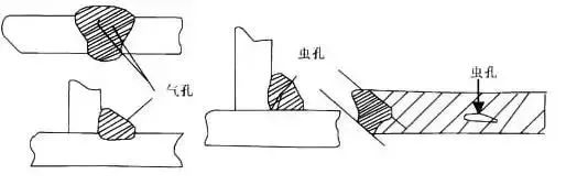
(8) Stomata
(A) Complete penetration (CJP) groove welds of butt joints where the welds are transverse to the calculated tensile stress, and no visible tubular pores are allowed. For all other groove and fillet welds, the sum of the diameters of visible tubular porosity equal to or greater than 0.8mm shall not exceed 10mm in any 25mm long weld and 20mm in any 300mm long weld.
X
(B) The frequency of occurrence of tubular pores in fillet welds is strictly prohibited to exceed 1 per 100mm of weld length, and the maximum diameter is strictly prohibited to exceed 2.5mm. The following exceptions are: For fillet welds connecting stiffeners to the web, the sum of the diameters of the tubular porosity must not exceed 10mm in any 25mm long weld, and must not exceed 20mm in any 300mm long weld.
X
(C) Complete penetration (CJP) groove welds of butt joints in a transverse relationship to the calculated tensile stress, with no tubular pores. For all other groove welds, the frequency of tubular pores shall not exceed 1 per 100mm of weld length, and the maximum diameter shall not exceed 2.5mm.
X
Note: “X” means suitable connection type, blank means not suitable.
3. Reasons and analysis of common weld defects and preventive measures
1. Stomata
Welding method
cause
Preventive measures
Manual arc welding
(1) The electrode is bad or wet.
(2) The weldment has moisture, oil or rust.
(3) The welding speed is too fast.
(4) The current is too strong.
(5) The arc length is not suitable.
(6) The thickness of the weldment is large, and the metal cooling is too fast.
(1) Select the appropriate electrode and pay attention to drying.
(2) Clean the welded part before welding.
(3) Reduce the welding speed so that the internal gas can easily escape.
(4) Use the appropriate current recommended by the manufacturer.
(5) Adjust the proper arc length.
(6) Carry out proper preheating work.
CO2 gas shielded welding
(1) The base material is dirty.
(2) The welding wire is rusted or the flux is wet.
(3) Poor spot welding and improper selection of welding wire.
(4) The dry elongation is too long, and the CO2 gas protection is not thorough.
(5) The wind speed is large and there is no wind shielding device.
(6) The welding speed is too fast and the cooling is fast.
(7) Spark splashes stick to the nozzle, causing gas turbulence.
(8) The gas has poor purity and contains many impurities (especially moisture).
(1) Pay attention to cleaning the welded part before welding.
(2) Select the appropriate welding wire and keep it dry.
(3) The spot welding bead must not be defective, and at the same time, it must be clean, and the size of the welding wire should be appropriate.
(4) Reduce the dry elongation length and adjust the appropriate gas flow.
(5) Install windshield equipment.
(6) Reduce the speed to let the internal gas escape.
(7) Pay attention to remove the welding slag at the nozzle, and apply a splash adhesion inhibitor to prolong the life of the nozzle.
(8) The purity of CO2 is more than 99.98%, and the moisture content is less than 0.005%.
Submerged arc welding
(1) There are organic impurities such as rust, oxide film, grease, etc. in the weld.
(2) The flux is wet.
(3) The flux is contaminated.
(4) The welding speed is too fast.
(5) Insufficient flux height.
(6) The height of the flux is too large, so that the gas is not easy to escape (especially when the particle size of the flux is fine).
(7) The welding wire is rusted or stained with oil.
(8) The polarity is inappropriate (especially when the docking is contaminated, it will cause pores).
(1) The weld should be ground or burned with flame, and then removed with a wire brush.
(2) about 300 ℃ drying
(3) Pay attention to the storage of the flux and the cleaning of the area near the welding part to avoid the mixing of sundries.
(4) Reduce the welding speed.
(5) The mouth of the flux outlet rubber tube should be adjusted higher.
(6) The flux outlet rubber tube should be adjusted lower, and the appropriate height is 30-40mm in the case of automatic welding.
(7) Change to clean welding wire.
(8) Change the direct current connection (DC-) to the direct current reverse connection (DC+).
bad equipment
(1) The decompression table is cooled, and the gas cannot flow out.
(2) The nozzle is blocked by spark spatter.
(3) The welding wire has oil and rust.
(1) When there is no electric heater attached to the gas regulator, an electric heater should be installed, and the flow rate of the meter should be checked at the same time.
(2) Clean nozzle spatter frequently. And coated with splash adhesion inhibitor.
(3) Do not touch the oil when the welding wire is stored or installed.
Self-shielded flux-cored wire
(1) The voltage is too high.
(2) The protruding length of the welding wire is too short.
(3) There is rust, paint and moisture on the surface of the steel plate.
(4) The drag angle of the welding torch is too inclined.
(5) The moving speed is too fast, especially for horizontal welding.
(1) Reduce the voltage.
(2) Use according to various welding wire instructions.
(3) Clean up before welding.
(4) Reduce the drag angle to about 0-20°.
(5) Adjust properly.
3. Undercut
Welding method
cause
Preventive measures
Manual arc welding
(1) The current is too strong.
(2) The welding rod is not suitable.
(3) The arc is too long.
(4) Improper operation method.
(5) The base material is dirty.
(6) The base metal is overheated.
(1) Use lower current.
(2) Select the appropriate type and size of welding rod.
(3) Maintain proper arc length.
(4) Use the correct angle, slower speed, shorter arc and narrower running method.
(5) Remove oil stains or rust from the base metal.
(6) Use electrodes with smaller diameters.
CO2 gas shielded welding
(1) The arc is too long and the welding speed is too fast.
(2) During fillet welding, the alignment of the electrode is incorrect.
(3) The vertical welding swings or poor operation, so that the two sides of the weld bead are insufficiently filled and undercut.
(1) Reduce the arc length and speed.
(2) During horizontal fillet welding, the position of the welding wire should be 1-2mm away from the intersection.
(3) Correct the operation method.
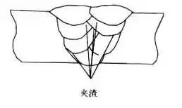
4. Slag inclusion
Welding method
cause
Preventive measures
Manual arc welding
(1) The front layer welding slag is not completely removed.
(2) The welding current is too low.
(3) The welding speed is too slow.
(4) The electrode swing is too wide.
(5) Poor weld combination and design.
(1) Thoroughly remove the front layer welding slag.
(2) Use higher current.
(3) Increase the welding speed.
(4) Reduce the swing width of the electrode.
(5) Correct the appropriate groove angle and clearance.
CO2 gas arc welding
(1) The base metal is inclined (downhill) to advance the welding slag.
(2) After the previous welding, the welding slag is not clean.
(3) The current is too small, the speed is slow, and the amount of welding is large.
(4) When welding by the forward method, the welding slag in the slot is much ahead.
(1) Place the weldment in a horizontal position as much as possible.
(2) Pay attention to the cleanliness of each weld bead.
(3) Increase the current and welding speed to make the welding slag float easily.
(4) Increase the welding speed
Submerged arc welding
(1) The welding direction is inclined toward the base metal, so the slag flows ahead.
(2) During multi-layer welding, the grooved surface is melted by the welding wire, and the welding wire is too close to the side of the groove.
(3) Slag inclusions are likely to occur at the welding starting point where there is a guide plate.
(4) If the current is too small, there is welding slag remaining between the second layers, and cracks are easily generated when welding thin plates.
(5) The welding speed is too low, which makes the welding slag advance.
(6) The arc voltage of the final finishing layer is too high, causing the free welding slag to stir up at the end of the weld bead.
(1) The welding should be reversed to the opposite direction, or the base metal should be changed to the horizontal direction as much as possible.
(2) The distance between the side of the slot and the welding wire should be at least greater than the diameter of the welding wire.
(3) The thickness of the guide plate and the shape of the slot must be the same as the base metal.
(4) Increase the welding current to make the residual welding slag melt easily.
(5) Increase the welding current and welding speed.
(6) Reduce the voltage or increase the welding speed. If necessary, the cover layer is changed from single-pass welding to multi-pass welding.
Self-shielded flux-cored wire
(1) The arc voltage is too low.
(2) The arc of the welding wire is improper.
(3) The welding wire sticks out too long.
(4) The current is too low and the welding speed is too slow.
(5) The first welding slag was not sufficiently removed.
(6) The first pass is poorly combined.
(7) The groove is too narrow.
(8) Welds slope downward.
(1) Adjust properly.
(2) Add more practice.
(3) Follow the instructions for use of various welding wires.
(4) Adjust the welding parameters.
(5) Completely clear
(6) Use proper voltage and pay attention to swing arc.
(7) Correct the appropriate groove angle and clearance.
(8) Lay flat, or move faster.
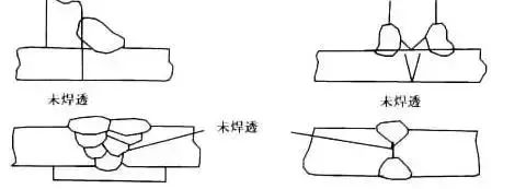
5. Incomplete penetration
Welding method
cause
Preventive measures
Manual arc welding
(1) Improper selection of electrodes.
(2) The current is too low.
(3) The welding speed is too fast, the temperature rise is not enough, and the speed is too slow, the arc impulse is blocked by the welding slag, and cannot be given to the base metal.
(4) The weld design and combination are incorrect.
(1) Use a more penetrating electrode.
(2) Use appropriate current.
(3) Use the appropriate welding speed instead.
(4) Increase the degree of grooving, increase the gap, and reduce the root depth.
CO2 gas shielded welding
(1) The arc is too small and the welding speed is too low.
(2) The arc is too long.
(3) Poor slotting design.
(1) Increase the welding current and speed.
(2) Reduce the arc length.
(3) Increase the slotting degree. Increase the gap and reduce the root depth.
Self-shielded flux-cored wire
(1) The current is too low.
(2) The welding speed is too slow.
(3) The voltage is too high.
(4) Improper arc swing.
(5) Improper bevel angle.
(1) Increase the current.
(2) Increase the welding speed.
(3) Reduce the voltage.
(4) Practice more.
(5) Use a larger slotting angle.
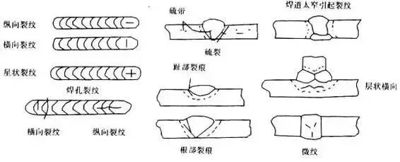
6. Crack

Welding method
cause
Preventive measures
Manual arc welding
(1) The weldment contains too high alloy elements such as carbon and manganese.
Welding method
cause
Preventive measures
Manual arc welding
(1) The weldment contains too high alloying elements such as carbon and manganese.
(2) The quality of the electrode is poor or wet.
(3) The restraint stress of the weld is too large.
(4) The sulfur content of the busbar material is too high, which is not suitable for welding.
(5) Insufficient preparation for construction.
(6) The thickness of the base metal is large and the cooling is too fast.
(7) The current is too strong.
(8) The first weld pass is insufficient to resist shrinkage stress.
(1) Use a low hydrogen electrode.
(2) Use suitable electrodes and pay attention to drying.
(3) Improve the structural design, pay attention to the welding sequence, and conduct heat treatment after welding.
(4) Avoid using bad steel.
(5) Preheating or post-heating should be considered during welding.
(6) Preheat the base metal and cool it slowly after welding.
(7) Use appropriate current.
(8) The welding metal of the first welding must fully resist shrinkage stress.
CO2 gas shielded welding
(1) The slotting angle is too small, and pear-shaped and weld bead cracks will occur during high-current welding.
(2) The carbon content of the base metal and other alloys are too high (weld bead and hot shadow zone).
(3) When multi-layer welding, the first layer of weld bead is too small.
(4) Improper welding sequence, resulting in excessive binding force.
(5) The welding wire is wet, and hydrogen penetrates into the weld bead.
(6) The sleeve plate is not tightly connected, resulting in unevenness and stress concentration.
(7) The cooling is slow (stainless steel, aluminum alloy, etc.) due to the excessive welding amount of the first layer.
(1) Pay attention to the coordination of the appropriate slotting angle and current, and increase the slotting angle if necessary.
(2) Use electrodes with low carbon content.
(3) The first welding metal must be sufficiently resistant to shrinkage stress.
(4) Improve the structural design, pay attention to the welding sequence, and conduct heat treatment after welding.
(5) Pay attention to the preservation of welding wire.
(6) Pay attention to the accuracy of the weldment combination.
(7) Pay attention to the correct current and welding speed.
Submerged arc welding
(1) The welding wire and flux used for the base metal of the weld are not properly matched (the base metal contains too much carbon, and the wire metal contains too little manganese).
(2) The weld bead is rapidly cooled to harden the heat-affected zone.
(3) The amount of carbon and sulfur in the welding wire is too large.
(4) The bead force generated in the first layer of multi-layer welding is insufficient to resist shrinkage stress.
(5) Excessive penetration or segregation during fillet welding.
(6) The welding construction sequence is incorrect, and the binding force of the base metal is large.
(7) The shape of the weld bead is inappropriate, and the ratio of the width of the weld bead to the depth of the weld bead is too large or too small.
(1) Use welding wire with high manganese content. When the base metal contains a lot of carbon, preheating measures should be taken.
(2) The welding current and voltage need to be increased, the welding speed should be reduced, and the base metal needs to be heated.
(3) Replace the welding wire.
(4) The welding metal of the first layer of weld bead must fully resist shrinkage stress.
(5) Reduce the welding current and welding speed and change the polarity.
(6) Pay attention to the prescribed construction methods and give instructions for welding operations.
(7) The ratio of weld bead width to depth is about 1:1:25, the current decreases and the voltage increases.
7. Deformation
Welding method
cause
Preventive measures
hand welding
CO2 gas shielded welding
Self-shielded flux-cored wire welding
Automatic submerged arc welding
(1) Too many welding layers.
(2) Improper welding sequence.
(3) Insufficient preparation for construction.
(4) Excessive cooling of the base metal.
(5) The base metal is overheated. (sheet)
(6) Improper weld design.
(7) Too much metal is welded.
(8) The restraint method is not accurate.
(1) Use electrodes with larger diameters and higher currents.
(2) Correct the welding sequence
(3) Before welding, use a fixture to fix the weldment to avoid warping.
(4) Avoid excessive cooling or preheating of the base metal.
(5) Use welding consumables with low penetration.
(6) Reduce the weld gap and reduce the number of slots.
(7) Pay attention to the welding size and do not make the weld bead too large.
(8) Pay attention to the fixing measures to prevent deformation.
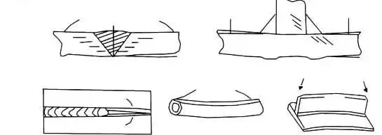
8. Other welding defects
Welding method
cause
Preventive measures
overlapping
(1) The current is too low.
(2) The welding speed is too slow.
(1) Use an appropriate current.
(2) Use a suitable speed.
Poor weld bead appearance
(1) Defective welding rod.
(2) The operation method is not suitable.
(3) The welding current is too high and the diameter of the electrode is too thick.
(4) The weldment is overheated.
(5) In the weld bead, the welding method is not good.
(6) The contact tip is worn.
(7) The extension length of the welding wire remains unchanged.
(1) Choose a dry electrode of appropriate size and good quality.
(2) Adopt uniform and appropriate speed and welding sequence.
(3) Select welding with appropriate current and diameter.
(4) Reduce the current.
(5) Practice more.
(6) Replace the contact tip.
(7) Maintain a fixed length and be proficient.
dent
(1) Improper use of welding rods.
(2) The electrode is wet.
(3) Excessive cooling of the base metal.
(4) Unclean electrodes and segregation of weldments.
(5) The carbon and manganese components in the weldment are too high.
(1) Use an appropriate electrode, if it cannot be eliminated, use a low-hydrogen electrode.
(2) Use dried electrodes.
(3) Reduce the welding speed and avoid rapid cooling. It is best to apply preheating or postheating.
(4) Use a good low hydrogen type electrode.
(5) Use electrodes with higher salinity.
partial arc
(1) During DC welding, the magnetic field generated by the weldment is uneven, which makes the arc deflect.
(2) The position of the ground wire is not good.
(3) The drag angle of the welding torch is too large.
(4) The extension length of the welding wire is too short.
(5) The voltage is too high and the arc is too long.
(6) The current is too large.
(7) The welding speed is too fast.
(1) Place a ground wire on one side of the arc, or weld on the opposite side, or use a short arc, or correct the magnetic field to make it more uniform, or switch to AC welding
(2) Adjust the position of the ground wire.
(3) Reduce the torch drag angle.
(4) Increase the extension length of the welding wire.
(5) Reduce the voltage and arc.
(6) Adjust to use proper current.
(7) The welding speed becomes slower.
burn through
(1) When there is slotted welding, the current is too large.
(2) The gap between the welds is too large due to poor grooving.
(1) Reduce the current.
(2) Reduce the weld gap.
Uneven weld bead
(1) The contact tip is worn, and the wire output swings.
(2) The welding torch operation is not proficient.
(1) Replace the welding contact tip with a new one.
(2) Do more practice exercises.
Welding tears
(1) The current is too large and the welding speed is too slow.
(2) The arc is too short and the weld bead is high.
(3) The welding wire is not aligned properly. (when fillet welding)
(1) Select the correct current and welding speed.
(2) Increase the arc length.
(3) The welding wire should not be too far away from the intersection.
Excessive sparks
(1) Defective welding rod.
(2) The arc is too long.
(3) The current is too high or too low.
(4) The arc voltage is too high or too low.
(5) The welding wire protrudes too long.
(6) The welding torch is too inclined and the drag angle is too large.
(7) The welding wire is excessively hygroscopic.
(8) The welding machine is in poor condition.
(1) Use dry and suitable electrodes.
(2) Use a shorter arc.
(3) Use an appropriate current.
(4) Adjust properly.
(5) Follow the instructions for use of various welding wires.
(6) Keep it as vertical as possible and avoid excessive tilting.
(7) Pay attention to the storage conditions of the warehouse.
(8) Repair, pay attention to maintenance on weekdays.
Weld bead zigzag
(1) The welding wire sticks out too long.
(2) The welding wire is twisted.
(3) Poor straight line operation.
(1) Use an appropriate length, for example, the solid wire extends 20-25mm when the current is large. The protruding length is about 40-50mm during self-shielded welding.
(2) Replace the wire with a new one or correct the twist.
(3) When operating in a straight line, the welding torch should be kept vertical.
The arc is unstable
(1) The contact tip at the front end of the welding torch is much larger than the core diameter of the welding wire.
(2) The contact tip is worn.
(3) The welding wire is curled.
(4) The rotation of the wire conveyor is not smooth.
(5) The groove of the wire conveying wheel is worn.
(6) The pressing wheel is not well pressed.
(7) The resistance of the conduit joint is too large.
(1) The core diameter of the welding wire must be matched with the contact tip.
(2) Replace the contact tip.
(3) Straighten the wire crimp.
(4) Oil the conveyor shaft to lubricate the rotation.
(5) Replace the conveying wheel.
(6) The pressure should be appropriate, too loose wire is bad, too tight wire is damaged.
(7) The bending of the catheter is too large, adjust and reduce the bending amount.
Arc occurs between nozzle and base metal
(1) Short circuit between nozzle, conduit or contact tip.
(1) The spark spatter sticks and the nozzle is too much to be removed, or use the ceramic tube with insulation protection of the welding torch.
Welding torch nozzle overheating
(1) The cooling water cannot flow out sufficiently.
(2) The current is too large.
(1) The cooling water pipe is blocked. If the cooling water pipe is blocked, it must be removed to make the water pressure rise and flow normal.
(2) The welding torch is used within the allowable current range and usage rate.
The wire sticks to the contact tip
(1) The distance between the contact tip and the base metal is too short.
(2) The resistance of the catheter is too large and the wire feeding is poor.
(3) The current is too small and the voltage is too large.
(1) Use an appropriate distance or a slightly longer arc to start the arc, and then adjust to the appropriate distance.
(2) Clear the inside of the catheter to enable smooth delivery.
(3) Adjust the appropriate current and voltage values.
Post time: Jun-07-2022